Control Valve Schematic Diagram Schematic Diagram Of Valve C
Valves valve instrumentation instrumentationtools sprinkler What are the parts of control valves and what are the accessories used Valve control final parts types valves element instrumentation industrial developed rs
Control Station and Control Valve in the Process Piping - Make Piping Easy
Pressure compensated schematic flow control hydraulic valves valve diagram orifice troubleshooting fig Industrial instrumentation and control (i&c): october 2010 Understanding control valve schematics: a comprehensive guide
Valves actuator positioner instrumentation functions principle instrumentationtools process breather
The control schematic of the control valve characteristic experimentalControl valve schematic diagram 6 hauptleistungsmerkmale des pneumatischen membran-einsitz-regelventilsValves instrumentation automationforum.
Control valve positioner circuit diagramHydraulic circuit diagram ppt, animation Pressure-compensated valvesSchematic diagram of valve control system..

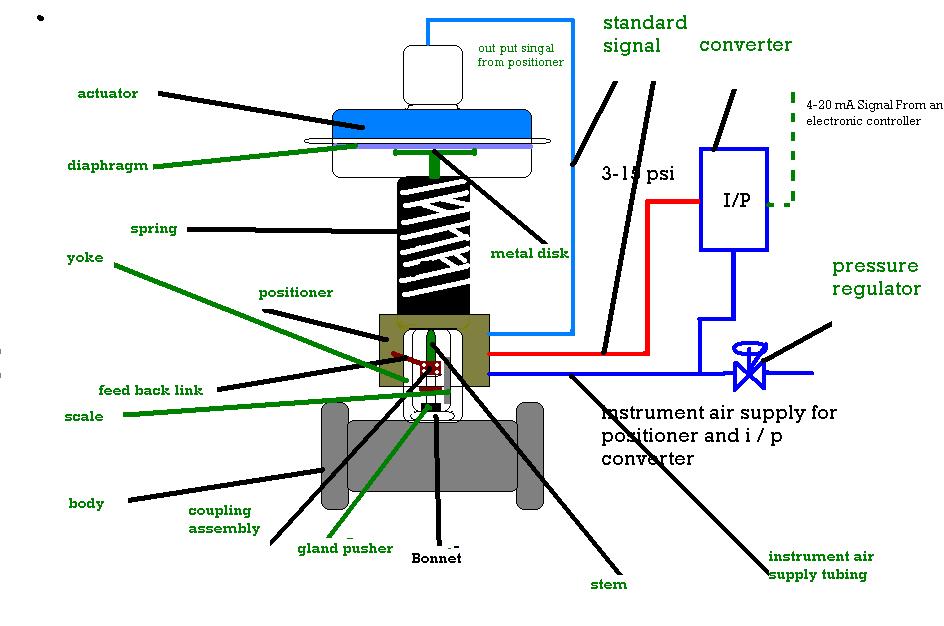
Control valve
Flow control valve circuit diagramSchematic diagram of the flow control valve Valve pneumatic sectional analysis electronics vibration fault detection[diagram] mack valve diagram.
Basic parts of control valves instrumentation toolsValves principle engineeringlearn How to test idle air control valve with multimeter (guide)Valve control actuator pneumatic diagram schematic air picture citizendium pd milton main pressure.

[diagram] hydraulic control valve diagram
Flow control valve schematic symbolValve positioners ️ control valve maintenance checklistSchematic diagram of valve control system..
Detented solenoid valve control circuit diagramControl station and control valve in the process piping Flow control valve: definition, types, components & working principleSchematic diagram of valve control system..
![[DIAGRAM] Pneumatic 3 Way Valve Diagram - MYDIAGRAM.ONLINE](https://i2.wp.com/www.hafner-pneumatik.com/images/catalog/3-2-way valves.PNG)
Valves actuator solenoid instrumentationtools functions instrumentation
Types of valvesSchematic representation of the control valve What are the parts of control valves and what are the accessories usedSchematic diagram of a control valve.
Types of control valves instrumentation tools[diagram] pneumatic 3 way valve diagram Valves types valve globe control flow schematic open close wide rate operation useEmbracing the advantages of butterfly valves – zhy casting.
![[DIAGRAM] Mack Valve Diagram - MYDIAGRAM.ONLINE](https://i2.wp.com/techblog.ctgclean.com/wp-content/uploads/Rotary-Valve1.jpg)
Valve positioners positioner pneumatic valves actuators principles cutaway
Valves instrumentation automationforumSchematic diagram of a control valve. Piping station process.
.

Industrial Instrumentation and Control (I&C): October 2010

Control Valve Positioner Circuit Diagram - Control Valves

Control Station and Control Valve in the Process Piping - Make Piping Easy

control valve schematic diagram - Circuit Diagram

The control schematic of the control valve characteristic experimental

Flow Control Valve: Definition, Types, Components & Working Principle

Flow Control Valve Circuit Diagram